Menu
Download
Data sheet
| Manufacturing number | BMS300200300 |
More info
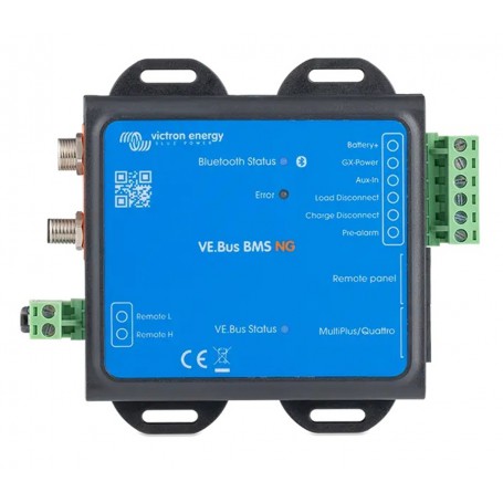
The next generation VE.Bus BMS NG
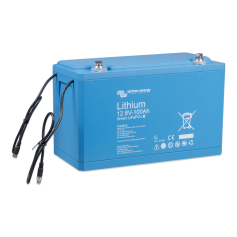
The VE.Bus BMS NG is a battery management system (BMS) for Victron Energy Lithium NG Batteries (not to be confused with the lithium smart batteries without NG). These batteries are based on Lithium Iron Phosphate (LiFePO4) batteries and are available in 12,8V, 25,6V and 51,2V in various capacity options. They can be connected in series, parallel, or a combination of both to create battery banks for system voltages of 12V, 24V, or 48V. A maximum of 50 batteries can be used when configuring a bank with 12V or 24V batteries, while up to 25 batteries can be used with 48V batteries. This allows for a maximum energy storage capacity of 192 kWh with 12V batteries, up to 384 kWh with 24V batteries, and 128 kWh with 48V batteries. For comprehensive details about these batteries, visit the Victron Lithium NG battery product page.
The VE.Bus BMS NG is designed to interface with and protect Victron Lithium NG batteries in systems that include a Victron VE.Bus inverter/charger1) or VE.Bus inverter1). It relies on this connection to perform key functions such as enabling/disabling charge and discharge based on battery conditions.
Based on the status of the Lithium NG battery, the BMS will:
• Generate a pre-alarm to indicate an imminent cell undervoltage condition
• Disable inverting in VE.Bus inverters or inverter/chargers via VE.Bus, and disconnect other loads via the Load Disconnect terminal in case of cell undervoltage
• Disable charging in VE.Bus inverters or inverter/chargers via VE.Bus, disable VE.Direct and VE.Can solar chargers via a GX device, and disconnect other chargers via the Charge Disconnect terminal in case of cell overvoltage, undertemperature, or overtemperature
Features
• Bluetooth Smart: The VE.Bus BMS NG includes Bluetooth Smart for wireless configuration, monitoring, and firmware updates via the VictronConnect App. Instant Readout shows key data such as SoC, battery temperature, warnings, and alarms directly in the device list, without needing to connect.
• Load disconnect output: Controls the remote on/off input of a BatteryProtect, Inverters, DC- DC converter, or other loads with remote on/off functionality. Due to its maximum output current of 1A, it can even control a high-current relay or a contactor.
Note that a non-inverting or inverting on/off cable may be required, please consult the manual.
• Charge disconnect output: Controls the remote on/off port of chargers such as the Smart Charger IP43, a Cyrix-Li-Charge relay, a Cyrix-Li-ct Battery Combiner or a BatteryProtect. Note that the Charge disconnect output is not suitable to power an inductive load such as a relay coil.
• Pre-alarm output: Triggers a visible or audible warning when battery voltage is low,activating at least 30 seconds before the Load Disconnect output is disabled due to cell undervoltage. Can drive a relay, LED, or buzzer. Maximum output current: 1A (not short-circuit protected).
• Remote on/off terminal: Allows remote control of the Load and Charge Disconnect outputs. When off, both outputs become free-floating, turning off connected loads and chargers.
• LED indicators: The VE.Bus BMS NG has three LEDs: a blue LED for Bluetooth status, a red LED for warnings and alarm errors and a VE.Bus status LED.
• Communication with VE.Bus products: MultiPlus, Quattro or Inverters connect to the ‘MultiPlus/Quattro’ port with a standard RJ45 UTP cable. The BMS disables inverting in the case of a cell under voltage condition and disables charging in the case of a cell over voltage or temperature condition.
• Communication with remote devices: : A GX device (such as a Cerbo GX), Digital Multi Control (DMC) panel or a VE.Bus Smart dongle (including any combination) can be connected to the BMS via the 'Remote panel' port. These accessories can all be used in combination with the BMS to remotely control the VE.Bus Inverter or inverter/charger switch state (on/off/charger-only).
• Auxiliary power input and output terminals: The BMS has a dedicated power output terminal (GX-Power) for a GX device and an auxiliary power input terminal (Aux-In)

 en
en
 de
de  es
es  fr
fr  it
it  nl
nl 


 United States.


